Busta 4 Trailer Mounting Instructions
Important Note: Busta 4.2 is designed for use with 12-volt negative earth towing vehicles complying with European lighting regulations. It provides trailer recognition and controls trailer lights. Please read these instructions carefully. Seek assistance if needed.
Compatibility
- Busta 4.2 is suitable for all 12-volt negative earth towing vehicles adhering to European lighting regulations.
- Any vehicle, regardless of its lighting regulations, can tow a trailer with a Busta 4.2.
Installation Precautions
- Do not install Busta 4.2 on the towing vehicle as it will incorrectly detect a trailer connection.
- Read the instructions thoroughly before starting.
- Gather all necessary tools and materials as listed near the end of this guide.
Wiring Details
- Busta 4.2 comes with a 600mm long 7-core cable (rated at 10 amps per wire).
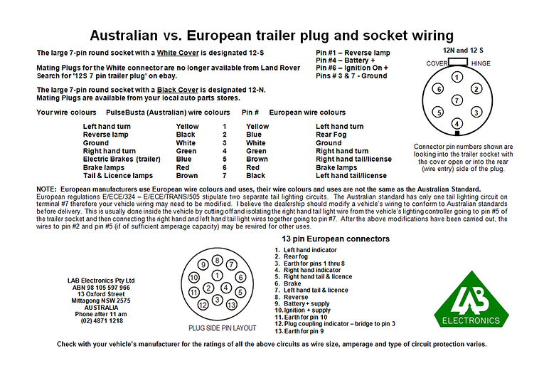
- Connect it to the trailer’s LEDs using the following wires:
- Yellow for left turn signal
- Green for right turn signal
- Red for brake light
- Brown for park/license plate light
- White for earth
- Each LED driver circuit supports up to 4 amps of LED current.
- Do not connect lamps (light bulbs) to the LED driver circuits on the trailer.
- Refer to the plug and socket wiring page for wire identification.
Temperature Warning
- Busta 4.2 can become very hot during operation.
- Ensure proper ventilation and avoid mounting on heat-sensitive materials like plastic.
Mounting Location
- Choose a high, dry location with good ventilation.
- Ensure it’s within reach of the existing trailer lighting wiring.
- You can redirect the trailer lighting cable to the chosen location and add a new cable from Busta 4.2 to the vehicle.
- Trim the outer sheath and insulation as needed for clean connections.
Installation Steps
- Disconnect the trailer from the vehicle and isolate any power sources in the trailer.
- Trailer LEDs
- Position Busta 4.2 in the selected location.
- Connect the trailer’s earth wire to the White wire from Busta 4.2.
- Solder the left turn signal wire to the Yellow output wire.
- Solder the right turn signal wire to the Green output wire.
- Solder the brake light wire to the Red output wire.
- Solder the tail/license plate wire to the Brown output wire.
- Vehicle End
- If adding a new cable, attach a trailer plug to the vehicle end.
- Connect the trailer’s earth wire to the White wire on Busta 4.2.
- Solder the left turn signal wire to the Yellow input wire.
- Solder the right turn signal wire to the Green input wire.
- Solder the brake light wire to the Red input wire.
- Solder the tail/license plate wire to the Brown input wire.
- Unused Wires
- If Black and Blue wires are not needed, cut them back and leave them disconnected.
- Otherwise, connect them to the remaining wires in your trailer cable for other purposes.
Ensure a secure and well-insulated connection for optimal performance and safety.
Testing Trailer LED Functionality
Instructions:
- Ensure all soldered connections are separated and not touching each other or any metal parts of the trailer.
- Reconnect power sources in the trailer.
- Turn off the vehicle’s ignition and lights.
- Connect the trailer to the vehicle.
- Turn on the ignition and verify that any previously blinking trailer LEDs have stopped.
- Confirm that the trailer indicator now functions with turn signals and hazard lights.
- Start the engine, switch on the park lights, and test the brake lights to ensure they are working correctly. Check for any lamp failure warnings.
- If there are lamp failure warnings, refer to the last page for troubleshooting.
- Once all trailer LEDs are functioning properly, turn everything off and insulate the bare soldered connections individually.
Cable Protection Guide
Insulating and Sealing
To safeguard your cables from moisture and dust, follow these steps:
- Apply Silicone Sealant: Cover all exposed cable ends with a thin layer of silicone sealant. Use a small screwdriver or a similar tool to ensure the sealant surrounds the wires.
- Weatherproofing: Enhance protection by wrapping self-amalgamating tape and/or heat shrink around the cable joins. This step ensures complete weatherproofing.
- Secure Attachment: Verify that the cable is securely attached to the trailer as needed.
Operational Tips
Remember these key points when connecting or disconnecting your trailer:
- Ignition and Lights Off: Always perform trailer connections or disconnections with the vehicle’s ignition and lights switched off. Doing otherwise may trigger malfunctions or unintended actions in your vehicle’s computer systems.
Busta 4.2 Trailer Lighting Unit: Installation and Maintenance Guide
What You’ll Need
- Busta 4.2 Trailer Lighting Unit
- Various hand and power tools
- Test light
- Soldering iron and solder
- Fixings for mounting and attaching cables to the trailer:
- Self-tapping screws
- Screws
- Nuts and washers
- ‘Pop’ rivets
- ‘P’ clips, etc.
- Electrical insulating tape
- Waterproofing materials:
- Silicone sealant
- Heat shrink and/or self-amalgamating tape
- Liquid electrical tape, etc.
Warranty Information
Busta 4.2 is covered by a two-year warranty against defects in parts and manufacture from the date of purchase. While we ensure that each unit is sealed to an IP-68 rating during manufacturing, please note that it is not covered against internal or external corrosion or damage caused by liquid or dust ingress once it’s in operation. We strongly recommend regular checks for possible liquid and dust entry points (such as nicks, cuts, abrasions, etc.) and sealing any openings with silicone sealant to prevent further damage. For assessment and repair, please return Busta 4.2 to LAB Electronics, as there are no user-serviceable parts inside.
Compliance Note
Busta 4.2 does not conform to E/ECE/324 – E/ECE/TRANS/505 regulations as it does not monitor the trailer’s turn signal LEDs. Therefore, it cannot inform the driver of any faults by turning off the trailer telltale in the instrument cluster. The responsibility always lies with the driver to ensure that all vehicle and trailer lighting is functioning correctly.
Troubleshooting
- A trailer lamp failure warning will appear in the vehicle when park and stop lights are used.
- The lamp check modules in most vehicles cannot check a trailer’s park and stop LED circuits.
- Load resistors inside Busta 4.2 and Euro units may develop heat and waste power but are not connected in most cases.
- If you receive a trailer lamp failure warning, follow these steps carefully:
- Undo the cable gland tail on the trailer end of the unit.
- Remove the two screws on the trailer end plate.
- Access the three wires inside the unit at the trailer end.
- On the trailer end of the unit, to undo the cable gland tail:
- Grip the 19mm (3/4in) body nut of the cable gland with a thin spanner.
- Loosen the tail with another 19mm (3/4in) spanner.
- Once loosened, undo the tail completely by hand and slide it along the cable away from the body.
- Remove the black silicone sealant from the two screw holes in the trailer end plate.
- Check that the O-ring seals under the screw heads are still intact.
- To access the rubber seal:
- Carefully move the end plate a short distance along the cable.
- Move the end plate back against the case of the unit.
- Grasp the seal and slide it along the cable as far as possible away from the body.
- Check that the sealing gasket on the end plate is undamaged.
- Fish out the three insulated wires with pre-stripped ends from inside the unit:
- White wire: Earth wire
- Black wire: Park circuit load resistor(s) (one resistor for Mk4, two for Euro)
- Red wire: Stop circuit load resistors (two resistors in all units)
- To address lamp failure warnings:
- For park circuit warning, connect the Black wire to the White wire.
- For stop circuit warning, connect the Red wire to the White wire.
- For both park and stop circuit warnings, connect all three wires together.
- Unscrew the end cap from the White wire and remove the sleeve from the Red and/or Black wires.
- Straighten the bared wire ends and twist the ends of the required wires together.
- Screw the end cap from the White wire over the twisted wires to terminate them.
- If only two wires are terminated, leave the sleeve over the unused wire. If all three wires are terminated, the plastic sleeves are no longer needed—dispose of them thoughtfully.
- Apply a small amount of neutral cure silicone sealant around the surface of the end plate gasket.
- Refit the end plate using the original screws (ensure O-rings are intact).
- Apply a small amount of neutral cure silicone sealant (black) to cover the screw heads as they were originally sealed.
- Slide the rubber seal along the cable and into the cable gland.
- Hand-tighten the tail onto the cable gland, using two 19mm (3/4in) spanners to prevent breaking the silicone sealant seal between the cable gland nut and end plate.