
Programming Your BECM (Body Electronic Control Module)
In your Land Rover, the BECM (Body Electronic Control Module) holds critical information that can be programmed for various functions. Here’s a breakdown of what you can do with your BECM:
1. Unlocking Your BECM
- Most BECM settings can be changed with standard diagnostic software.
- Unlocking the EKA code or FOB code for remote access requires specialist software and disassembly.
2. EKA Code Recovery
- If locked out with an alarm, try entering the EKA code.
- If you don’t have it, contact your Land Rover dealer for retrieval.
- Note: A faulty driver’s door latch may hinder EKA input.
3. Resolving Alarm Lockout
- If you can’t deactivate the alarm lockout, consider sending your BECM for service.
- In Australia, this process is straightforward and affordable.
- However, international shipping can be costly, so we provide instructions for removing and servicing the Logic Board.
4. Common BECM Programming Options
- BECM Alarmed Status: Reset the BECM to a non-alarmed status.
- EKA Lockout Status: Reset the EKA lockout to normal.
- EKA Number: Retrieve the Emergency Key Access Number (EKA) for your vehicle.
- Engine: Select the engine management system based on your vehicle’s year and model.
- EMS Code: Synchronize codes between BECM and Engine Management System (EMS) ECU to ensure proper immobilization.
- BECM Status: Understand the electronic lock on your BECM and its implications.
For unlocking your BECM, you can use RovaCom software with the SM035 module, available at https://blackbox-solutions.com/shop/product/sm035. Ensure you review and confirm all BECM data before locking it, as the process is irreversible.
Please let us know if you have any further questions or need assistance with your BECM programming.
Programming Your BECM: Simplified Instructions
Unlocking and programming your BECM (Body Electronic Control Module) can be done using diagnostic software. Here’s what you need to know:
1. BECM Unlocking:
- If your BECM is in alarm and locked, try entering the EKA code. If you don’t have it, contact your Land Rover dealer for retrieval.
- Note: A driver’s door latch failure can trigger alarm and lockout.
2. Alarm and Lockout Resolution:
- If the BECM remains in alarm and lockout, you may need to remove and send either the entire BECM or just the Logic Board.
- Sending the entire BECM within Australia is manageable, but it’s costly from outside Australia. We provide instructions for removing the smaller, lighter Logic Board.
3. Common BECM Programming:
- BECM Current Alarmed Status: Reset the BECM status from alarmed to not alarmed. Unknown indicates an invalid value.
- Current EKA Lockout Status: Reset the EKA lockout status to normal. Unknown indicates an invalid value.
- EKA Number: Emergency Key Access Number, available on unlocked BECMs. Must be 4 characters long, with unique digits.
- Engine Selection: Choose between different engine management systems.
- EMS Code: Necessary for engine immobilization and synchronization between BECM and EMS ECU.
4. BECM Lock Status:
- BECMs are locked electronically after programming at the factory. Unlocking is possible with RovaCom software using SM035. It’s okay to leave it unlocked for normal use.
5. FOB Code:
- The FOB code is vital for key fob functionality. Obtain it through your dealer by providing the lockset barcode.
- If the barcode is incorrect, you may need to replace the lockset.
6. Additional Functions:
- We can disable the alarm, passive immobilization, change engine types, and more.
7. General BECM Settings:
- Please note: Changing the settings of 15 or 16 from their programmed Australian settings may contravene the Australian Design Rules.
8. Owner’s Agreement:
- Please copy, complete, sign, and return this agreement before any BECM programming.
I, ______________________________________________________ as the rightful owner of the Range Rover with Vehicle Identification Number (VIN) of ________________________________________ hereby grant full legal immunity to the re-programming for any consequences arising from the adjustment of settings within the vehicle’s Body Electronic Control Moduel (BECM).
Signature: _________________________________________________
Date: _________________/__________________/_________________
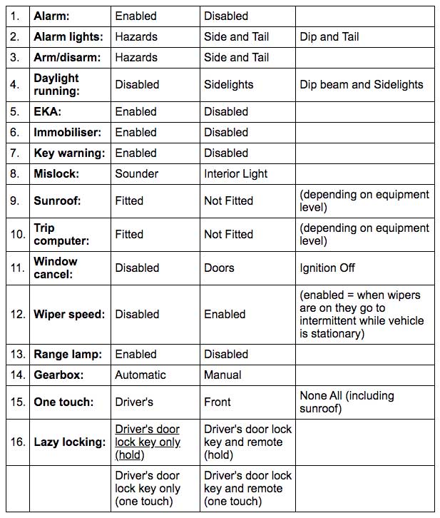
Settings Overview:
- Alarm: Enable/disable the alarm.
- Alarm Lights: Change visual output for alarm activation.
- Arm/Disarm: Alter visual notification for alarm arming/disarming.
- Daylight Running: Select headlamps, sidelights, or disable daytime running lights.
- EKA: Enable/disable Emergency Key Access (EKA) code input.
- Immobilizer: Turn on/off passive immobilization.
- Key Warning: Enable warning gong for keys left in the ignition.
- Mislock: Choose error notification method on alarm arming.
- Sunroof: Indicate if the vehicle has an electric sunroof.
- Trip Computer: Specify if a trip computer is installed.
- Window Cancel: Manage window/sunroof operation after ignition off.
- Wiper Speed: Control wiper behavior when the vehicle stops.
- Range Lamp: Enable/disable range selector back lamp function.
- Gearbox: Specify manual or automatic transmission.
- One Touch: Define which windows have one-touch functionality.
- Lazy Locking: Adjust conditions for lazy locking.
Programming your BECM is essential for customising your Land Rover experience.
Removing and Installing the BECM (Body Electronic Control Module)
Introduction: This guide explains how to safely remove and reinstall the Body Electronic Control Module (BECM) in your vehicle. Follow these steps carefully to ensure a smooth process. Before you begin, make sure you have your radio code handy.
Step 1: Removing Engine Bay Fuses
- Open the engine bay fuse box.
- Remove the three large 60 amp (blue) fuses. Start with the rear one, followed by the middle one, and finish with the front one. These fuses power the three brown wires on the BECM’s exterior.
Step 2: Locating and Preparing the BECM
- Locate the BECM, a large black box with a finned aluminum lid under the driver’s seat.
- Remove the plastic seat trims around the seat base.
Step 3: Removing the Seat and Disconnecting Cables
- Use a T50 Torx bit and suitable driver to loosen the rear two seat mounting bolts.
- Remove the front two seat mounting bolts.
- Slightly tip the seat backward to unplug the cables from underneath.
- Lower the seat and remove the two rear seat mounting bolts.
- Prepare the rear seat for the front seat by clearing it and placing sturdy cardboard or carpet on the seat base.
- Carefully lift the front seat, tilt it sideways, and place it on its left-hand side onto the rear seat with the headrest furthest away from you. Note: No need to unbolt the seatbelt.
Step 4: Removing the Plastic Duct
- Unscrew the plastic duct on top of the BECM and remove it.
Step 5: Disconnecting Power Terminals
- Undo the three 10mm power terminal connection nuts (brown wires) on the BECM’s outer face (next to the fuses). Note their order for reassembly.
Step 6: Disconnecting the Earth Terminal
- Undo the 10mm earth terminal connection nut (black wire) to the left of the three nuts removed in step 5.
Step 7: Removing Mounting Nuts
- Undo the three 10mm nuts that secure the BECM to the vehicle floor.
Step 8: Disconnecting Multi-Plugs and Removing BECM
- Disconnect all multi-plugs from the BECM.
- Carefully remove the BECM from the vehicle.
Reinstallation: To reinstall the BECM, follow the reverse of the removal procedure. Ensure you follow the EKA (Emergency Key Access) and Power Up procedure and then reprogram the radio.
You are away: With the BECM successfully removed and reinstalled, your vehicle is now ready to use. As an additional note, while the BECM is removed, locate the earth stud on the floor behind the seat, under the carpet. Follow the black earth wire, remove the nut and ring terminals, thoroughly clean them, and refit them securely, especially removing any grey paint on the stud face.
Emergency Key Access (EKA) and BECM Powering for Range Rover
Unlocking Your Vehicle with EKA
If you’ve locked your Range Rover using the remote and find yourself without it, don’t worry. You can unlock your vehicle and disarm the alarm by following these steps:
- Use your key to unlock the driver’s door.
- When you open the door, the alarm will sound twice. Insert your key into the ignition and try to start the engine. If the engine doesn’t crank and the message center displays ‘ENGINE DISABLED PRESS REMOTE OR USE KEY CODE,’ proceed to the next step.
- Close the driver’s door, and ensure that all doors, the tailgate, and the hood are securely closed. This step is crucial; otherwise, EKA won’t work.
- Turn the key to the lock position. Please note that you cannot enter the code if ‘KEY CODE LOCKOUT’ is displayed on the message center.
- Enter the code by turning the key to the lock or unlock position. Each turn of the key will cause the side lamps warning lamp to flash, indicating that the key turn has been recognized.
- Enter the first digit. For example, if the first digit is 2, turn and release the key two times in the unlock direction.
- Enter the second digit. If the second digit is five, turn and release the key five times in the lock direction.
- Enter the third digit. If the third digit is four, turn and release the key four times in the unlock direction.
- Enter the fourth digit. If the fourth digit is two, turn and release the key two times in the lock direction.
- Turn the key to the unlock direction. If you’ve entered the code correctly, all doors and the tailgate will unlock, and the alarm will be partially disarmed.
Once the EKA code is entered, the security LED will continue flashing to indicate that the alarm is partially disarmed and will trigger if the hood is opened. If you enter the code incorrectly, a mislock will sound on the final unlock turn, and the remaining doors and the tailgate will stay locked with a partially armed alarm. After five incorrect attempts, there will be a ten-minute ‘lockout,’ and ‘KEY CODE LOCKOUT’ will display on the message center.
If you make a mistake while entering the code, open either of the front doors, and a mislock will sound. Close the door, lock it with the key, and start the code entry again. This won’t count as an incorrect EKA entry.
While the vehicle is in EKA mode, pressing the unlock button on the remote will unlock all doors and disarm the alarm. The lock button won’t function during EKA code entry.
EKA Procedure for Vehicles from 96MY
For vehicles from 1996 onward, the EKA procedure is similar, with a few exceptions:
- If the vehicle wasn’t locked with the remote, turn the key four times to the lock position in step 4.
- The number of incorrect attempts is reduced to three, and the lockout period is increased to thirty minutes.
Powering Up Your P38 BECM
When you need to power up your P38 BECM, follow these steps:
- In the engine bay fuse box, remove the three large 60-amp (blue) fuses. Start with the rear one, then the middle one, and finally the front one. These fuses supply power to the three brown wires on the outside of the BECM. If you’re removing and refitting the BECM, leave the battery terminals connected to keep power to the other computers.
- With a charged battery fitted and the BECM reconnected, proceed to the next step.
- Open the driver’s door and leave it open.
- Insert only one key/remote into the steering column lock, but do not turn it. Multiple keys/remotes near the ignition lock can cause signal interference.
- Reinstall the three fuses in reverse order: front one first, middle one second, and rear one last.
As the BECM powers up (with the key in the steering column and the driver’s door open), it should perform a friendly mobilization sequence. If it doesn’t, repeat the fuse removal and reinstallation process as described above.
If the other doors unlock at this point, close and open the driver’s door or any other door. If a door isn’t opened within one minute, the vehicle will automatically relock all doors and arm the alarm.
You will now need to re-synchronize the remote(s) with the BECM. Insert the remote key into the driver’s door lock, turn it to lock or unlock, and quickly return it to the rest position. Quickly push either button on the remote several times until all the doors start locking and unlocking with the remote buttons.
Unlock the vehicle and open the driver’s door (or any door). If a door isn’t opened within one minute, the vehicle will automatically relock all doors and arm the alarm.
Finally, insert the key into the ignition lock, turn it, and start the engine. Recode the radio, reset the windows, and sunroof as needed.
Good luck, and any feedback is appreciated.
Issue with Front Door Functions in P-38 Range Rover
Problem Description:
- Symptoms: Front door central locking, window, and mirror functions are not working.
- Possible Cause: Fuse 9 and 22 on the BECM may be blown, indicated by a fuse warning in the instrument cluster.
- Outstation Swap: If a faulty outstation is suspected, you can swap the left and right outstations as they are identical.
- Sill Channel Wiring Issue: There is a known issue where moisture in the sill channel can cause corrosion in the wiring harnesses, especially the red wires. This can lead to high ohms readings or open circuits in affected wires. Visually inspecting these wires may not reveal the issue. Cut out the corroded section and replace it with soldered and insulated connections at both ends. Verify continuity by testing with a multimeter while moving and stretching the repaired wires.
- Continuity Test: With both ends disconnected, ensure good continuity (very low ohms) when testing each wire with a multimeter by back-probing the terminals. When moving the sill loom, there should be no resistance between a wire and earth, except for the black earth wires, which should have very good continuity to earth.
- Door Outstation Wiring: Each door outstation has 8 wires in the black 16-pin connectors (C755R and C755L). Here are the key wire functions:
- Purple wire with blue trace (terminal 6): Battery power from Fuse 22.
- Purple wire with black trace (terminal 10): Battery power from Fuse 9.
- Two black earth wires (terminals 7 and 9).
- Purple wire with orange trace (terminal 3): Carries mirror position data.
- Orange wire with green trace (terminal 15): Carries serial data direction signals.
- Light green wire (terminal 13): Carries the serial data.
- Red wire (terminal 14): Carries the clock (or timing) signals.
BECM to Right Front Door Outstation:
- Connectors:
- C326 (C1285): Blue 20-pin connector on the bottom row at the front of the BECM.
- C323 (C1284): Grey 12-pin connector on the top row at the front of the BECM, with power wires in terminals 2 and 12.
- Earth Point: E328, located on the side of the wheel arch under the seat latch mechanism on the right-hand side of the luggage space.
BECM to Left Front Door Outstation:
- Connectors:
- C362 (C1286): Black 16-pin connector on the bottom row at the front of the BECM, with terminals 1, 8, 9, and 10. The harness runs behind the center console, behind the left seat, and into the left side sill channel up to a 12-way black connector located at the A-pillar end of the flex tube going to the door. It then goes up through the tube and door to the outstation.
- C361 (C1291): White 18-pin connector on the inside at the front of the BECM, with power wires in terminals 6 and 10.
- Note: Under the left seat, wires have been found to be short-circuited to the seat base mountings.
Important Information:
- In Land Rover circuit diagrams, Cxxx represents connector numbers for Range Rovers up to and including 1999, while the numbers in brackets (Cxxxx) are for 2000 onwards.
Please ensure safety precautions when working with electrical components, and consult your vehicle’s manual for specific details and diagrams.
Troubleshooting Intermittent Engine Non-Start Issues
Section 1: Electrical Connection Concerns
If you’re experiencing intermittent non-start issues due to engine immobilization, it might be related to the electrical connections. Gold-plated terminals used to connect the BECM (Body Electronic Control Module) to the ECM (Engine Control Module) can be susceptible to corrosion between the gold plating and the base metal of the terminal. Disconnecting and reconnecting them may provide a temporary fix, as it can displace the insulating corrosion. However, for a permanent solution, apply a small amount of contact treatment solution specifically designed for gold contacts. This has proven effective in preventing further problems.
Important Note: Always use contact treatment solutions intended for gold contacts.
Where to Find Contact Treatment Solution: Look for contact treatment solutions at electronics stores in your area. For example, Jaycar stores in Australia and New Zealand offer Deoxit, a contact cleaner and rejuvenator, available in both aerosol cans and solution kits (NS-1434 Aerosol can or NS-1436 Solution Kit).
Section 2: Terminals Requiring Treatment
For different ECM types, you may need to treat specific terminals:
BOSCH Motronic ECM:
- Pin 5 of the 16-pin green connector on the BECM connects to pin 33 of the ECM through pin 1 of the body/engine harness connector.
- Pin 20 on the ECM connects to pin 5 of the 20-pin green connector on the BECM through pin 15 of the body/engine harness connector.
- The BOSCH Motronic ECM connector is the 40-pin second from the end.
GEMS ECM:
- Pin 5 of the 16-pin green connector on the BECM connects to pin 26 of the 36-pin red connector of the ECM through pin 1 of the body/engine harness connector.
- Pin 22 of the 36-pin black connector on the ECM connects to pin 5 of the 20-pin green connector on the BECM through pin 4 of the body/engine harness connector.
- The body/engine harness connector is located under the coolant expansion tank in the engine bay.
Section 3: Diagnosing MIL (Check Engine Light) Issues
If you’re not getting the check engine light (MIL) in the instrument cluster, it could be due to a problem with the EMS (Engine Management System) code not reaching the EMS unit or not receiving the MIL signal back.
For GEMS: The engine will crank only when there’s a MIL signal. Ensure the connectors on the EMS are removed and refitted a couple of times. If the issue persists, unclip the coolant expansion tank and reconnect the connector(s) underneath it.
For BOSCH: The engine will crank without injection or spark if there’s no MIL signal. Perform the same connector reseating process as for GEMS.
Note: The MIL light must be on for the BECM to crank the engine with GEMS. With BOSCH, the engine will crank but not start.
Additional Information: When turning the ignition switch to position 3 (crank), the relays you hear clicking in the BECM are not related to cranking the engine. The starter relay is silently switched by an IC in the BECM only when there’s a MIL signal (GEMS), no alarm or immobilization, and the gearbox is in park/neutral.
Check Gear Selector: A common issue is the gear selector switch failing due to condensate from the A/C drain. Ensure that the gear indication displayed in the instrument cluster is correct.
For GEMS: You can bypass the starter relay to check for a faulty relay, blown crank fuse, or starter motor issues. Find the 10 pin yellow connector on the BECM, and earth terminal 2 (white wire with a red trace). If everything else is okay, the engine will crank, and with the ignition switched on, it will start.
Caution: Bypassing the starter relay disables the Park/Neutral inhibit, and if the gearbox is in gear, the Range Rover may move.
Section 4: Further Assistance
If the non-start problem persists, please refer to the GEMS Mobi4 section for additional guidance.
Logic Board Removal and Installation
Overview: This guide outlines the steps to safely remove and reinstall the logic board inside a BECM (Body Electronics Control Module). Follow these instructions carefully to ensure proper handling of the components.
Removal Procedure:
Step 1: Remove the Lid
- Place the BECM on a clear workbench.
- Use a T8 Torx bit to remove all 8 coarse-threaded screws around the aluminum lid’s outer edge.
- Store these screws in a labeled plastic bag.
Step 2: Access the Interior
- Use either a T8 or T10 Torx bit to remove all 11 machine-threaded screws in the middle of the aluminum lid.
- Remove the lid and place the screws in a separate labeled bag.
Step 3: Prepare for Safe Work
- Ensure you are working on a static-safe work mat.
- Wear a wrist strap to prevent static discharge.
- Adhere to static-safe work principles, as detailed here.
Step 4: Disconnect Ribbon Cables
- Locate 4 gray ribbon cables with red header connectors along three edges of the upper PCB (power board).
Step 5: Carefully Disconnect
- Carefully unplug each of the 4 connections by pulling straight up on the red header connectors.
- Ensure even pressure to avoid bending pins as they separate.
Step 6: Prepare the Power Board
- Bend the ribbon cables backward, moving the disconnected header connectors outside of the BECM’s outer case.
Step 7: Access the Logic Board
- Lift the power board and hinge it back on its wires approximately 140 degrees, towards the side with the fuse box.
- This provides access to the screws holding the logic board in the bottom of the case.
Step 8: Remove Logic Board
- Use a T8 Torx bit to unscrew the 7 coarse-threaded screws securing the logic PCB to the bottom of the BECM box.
- Remove the lower PCB (Logic Board) and store the screws in a labeled bag.
Packaging for Transport:
- Place the Logic Board in a static-safe bag for safekeeping during transport. Ensure it’s securely packed to prevent damage.
Important Note: You can typically find suitable static-safe bags at computer repair stores (such as PC motherboard anti-static bags). Additionally, consider obtaining a protective box and suitable packaging for safe transportation.
Reinstallation: To reinstall the logic circuit board, simply follow the above steps in reverse order, ensuring a secure and safe reassembly of your BECM.
Remotes for Your Vehicle
Programming Your Remotes:
- To program a remote to your vehicle’s Body Electronic Control Module (BECM), it must have the same lockset barcode and FOB code.
- Remotes are categorized into four classes (1, 2, 3, 4), but only classes 1 and 2 operate seat and mirror memory functions (if available).
Understanding the FOB Code:
- The FOB code is a 3-part code that uniquely identifies key fobs (remotes) for your vehicle.
- Each key fob transmits its encrypted electronic ID code (FOB CODE) when pressed.
- The BECM decrypts the received code and compares it to the stored FOB CODE to validate the key.
- For security reasons, this information is accessible only on unlocked BECMs (refer to BECM STATUS in the BECM programming section).
- The FOB CODE is derived from the manufacturer’s lockset barcode, a 14-digit alphanumeric number found on a label that comes with every new key fob or lockset.
- Obtain the lockset barcode from your local Land Rover dealership by providing your vehicle’s VIN number.
- If the barcode is incorrect due to a previous lockset replacement, you have two options:
- Replace the entire lockset and use the new barcode for programming.
- We can provide a new remote (single remote with its lockset barcode), but for additional remotes, you’ll need to order from a Land Rover dealer. Ensure they are of a different class than your existing remote (e.g., 1 or 2).
Mechanical Key:
- Remotes supplied by us (or Land Rover) include a mechanical key, likely not compatible with your locks.
- If you have a non-working remote, we can swap the mechanical key.
- We also offer blank mechanical keys, which can be cut to fit your locks if you provide a working mechanical key.
Frequency Compatibility:
- Some regions use 315 MHz, while others use 433 MHz for remote frequencies.
- It’s important to know the frequency your Range Rover’s receiver module uses.
- Most remotes we have are 315 MHz, so if your receiver is 433 MHz, it will require replacement for compatibility with a new remote.
Remote Repairs:
- We offer spare parts and new cases for P-38 remotes.
- Repairs are possible for remotes that are not corroded or water-damaged.
In summary, programming your remote requires matching lockset barcodes and FOB codes. Understand the FOB code’s origin, consider mechanical key compatibility, and be aware of your vehicle’s receiver module frequency. We also offer remote repairs and replacement options if needed.