
Are You Dealing with a Damaged Data Connector?
If your diagnostic communication is hampered by a corroded or damaged data connector, we have the solution for you. Our Replacement Data Connectors come with new terminals and wires, ready to get your vehicle back on track.
Ordering Information
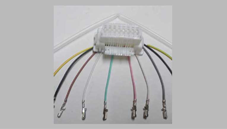
This package includes a brand-new data connector with ten terminals, each with wires crimped onto them.
Preparation
These instructions are specifically designed for the P-38 Range Rover, but they may apply to similar vehicles with slight variations in the number of terminals in their data connectors.
Safety Caution
Before you begin, please note that the wire in chamber 16 (coloured Brown) always carries battery voltage. To ensure your safety, turn off the ignition and remove the Engine Bay Fuse labeled #33 (a 5-amp fuse).
Step-by-Step Replacement
- Identify and Cut: Determine the most corroded terminal and cut it off right at the terminal end of the wire. Strip approximately 6 mm of insulation and examine the wire for cleanliness. If there is any sign of corrosion, trim the wire’s end and strip it again, repeating this process until you reach a clean, bright wire.
- Wire Length Check: Ensure that you have enough usable wire length to reattach the connector when you’re finished. If you’ve cut off too much wire length while cleaning, you may need to extend the wire by soldering a short length of suitable wire.
- Heat Shrink Preparation: Cut the supplied heat shrink into ten pieces (to match the number of joins to insulate). Slide one (or two, if necessary) pieces onto each wire.
- Solder and Insulate: Select a wire and strip about 6 mm of insulation from the end. Solder the two bare wire ends together, and once it cools, slide the heat shrink over the join. Finally, fit the terminal into the appropriate chamber of the new Data Connector terminal block. Repeat this process for each wire individually until all the new wires and terminals are correctly positioned.
- Insulate with Heat Shrink: Place the heat shrink over each bare wire join, then use a heat gun to apply hot air, shrinking the material in place to insulate the joins from each other.
- Connector Installation: Position the new connector into its original location and replace the previously removed fuse. Your diagnostic equipment will now be able to communicate with your vehicle once more.
Note
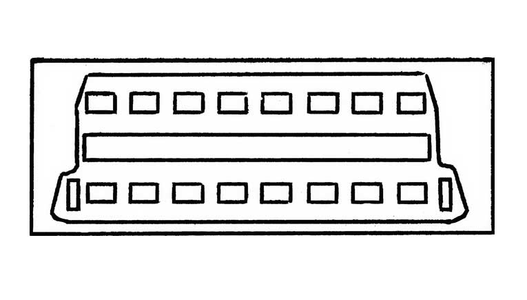
- Terminals can only be inserted or removed from the Data Connector terminal block when the side flaps are open, as this is one of the two anti-backout features designed to prevent terminal displacement when the diagnostic plug is connected.
- If you need to remove a fitted terminal, open the side flap and gently insert a flat-blade jeweler’s screwdriver into the front of the chamber. Slightly lift the second of the anti-backout tabs to unlock the terminal. You can explore an empty chamber to familiarize yourself with the tab and its operation.